RPi Action Camera
Why?
ROS Nodes
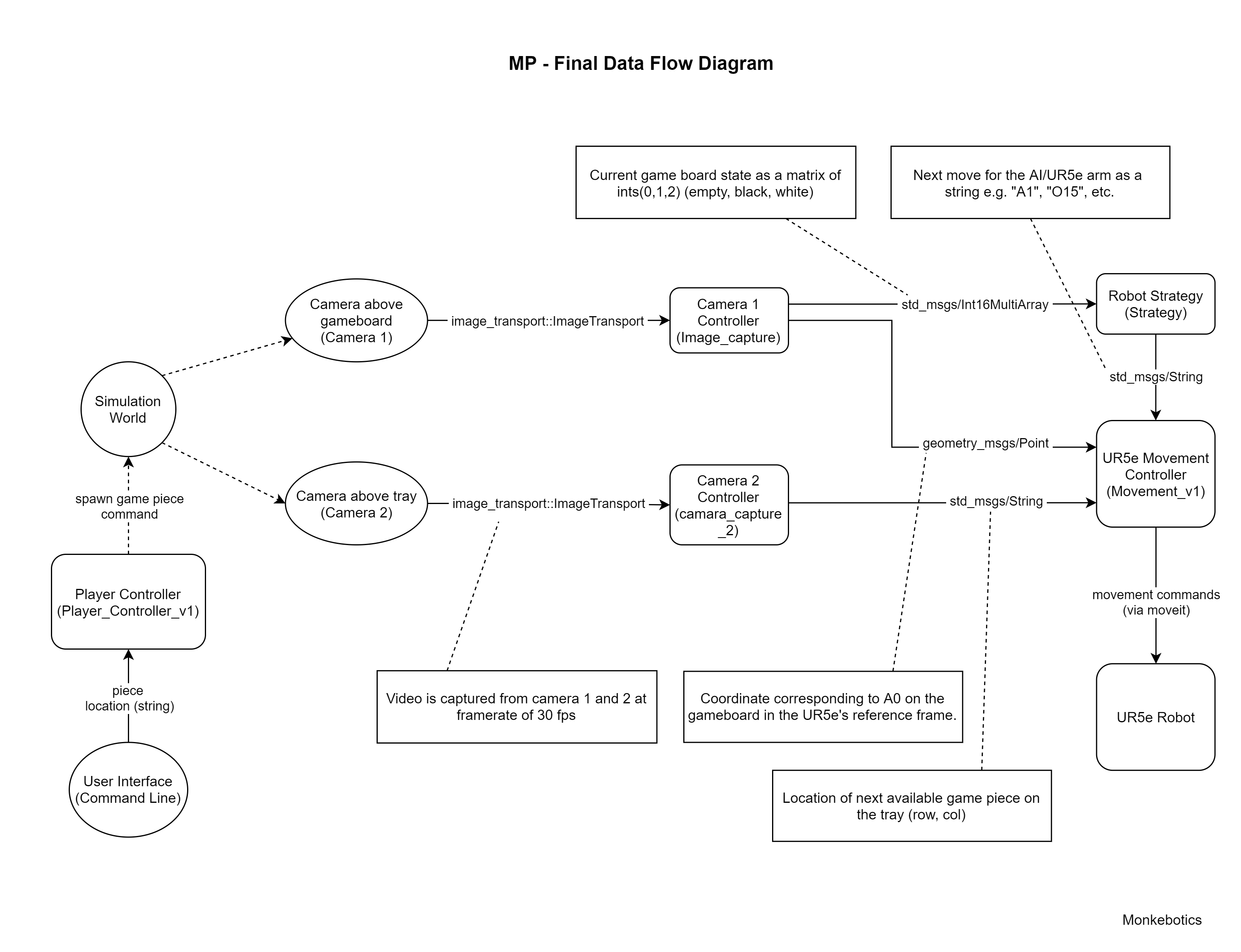
The final demo consisted of 5 ROS nodes, each performing a particular task.
- Player Controller:
- Camera Node 1: takes in an image of the game board and outputs in current state and a reference location(A0).
- Camera Node 2: takes in an image of the pieces tray and outputs the location of the next piece to pick up.
- Robot Strategy/AI: takes in the current state of the board and outputs the coordinates for the next move.
- UR5e Movement Controller:
Overview

Vision
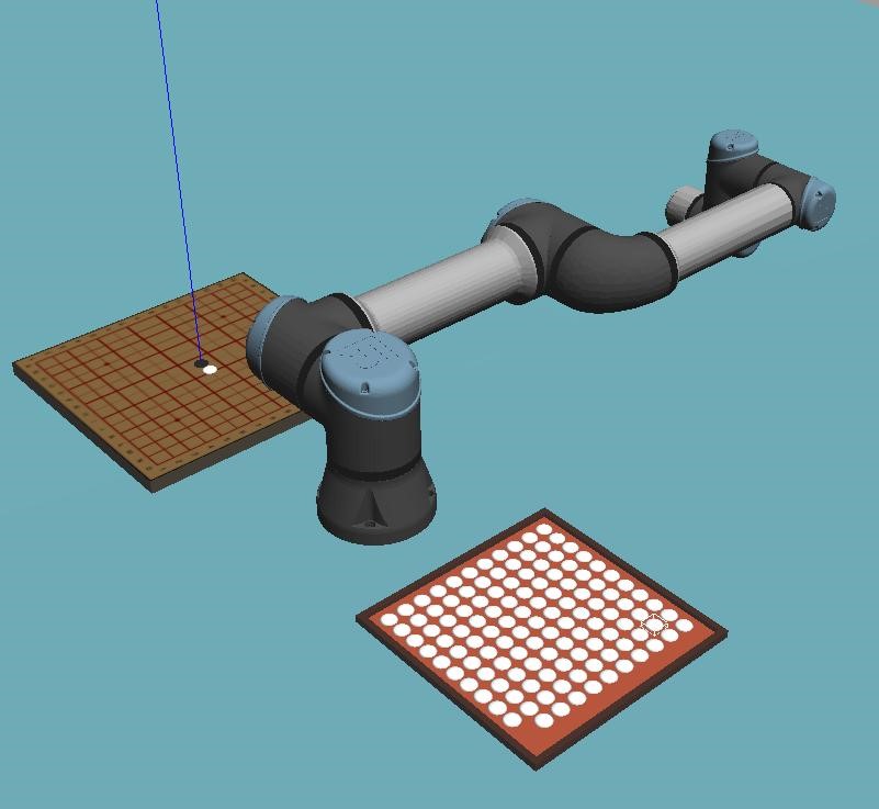
For the simulation, there were 2 cameras that were set up - 1 located above the game board(camera 1) and another over the tray containing the pieces(camera 2).
Strategy/AI1
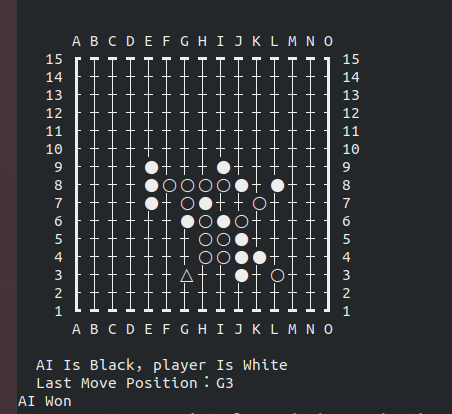
The robot simply used a MinMax based strategy to play.

Performance and Testing
Simplifications Made for Simulation
Due to limitations of time, several simplifications were made to the simulation to keep the environment as steady as possible2. The idea was that once a simplified version of the simulation worked satisfactorily, the simplifications could be removed incrementally. Some of these are discussed below.
-
Assets such as the tray and game board were made stationery(i.e. were omitted from the dynamics simulation). In addition, game pieces that were not being moved or about to be moved soon were made stationary(only on the game board) as the placement accuracy needed to be measured reliably. The primary reason for this was due to a limitation in the implementation of the e-pick in simulation3.
-
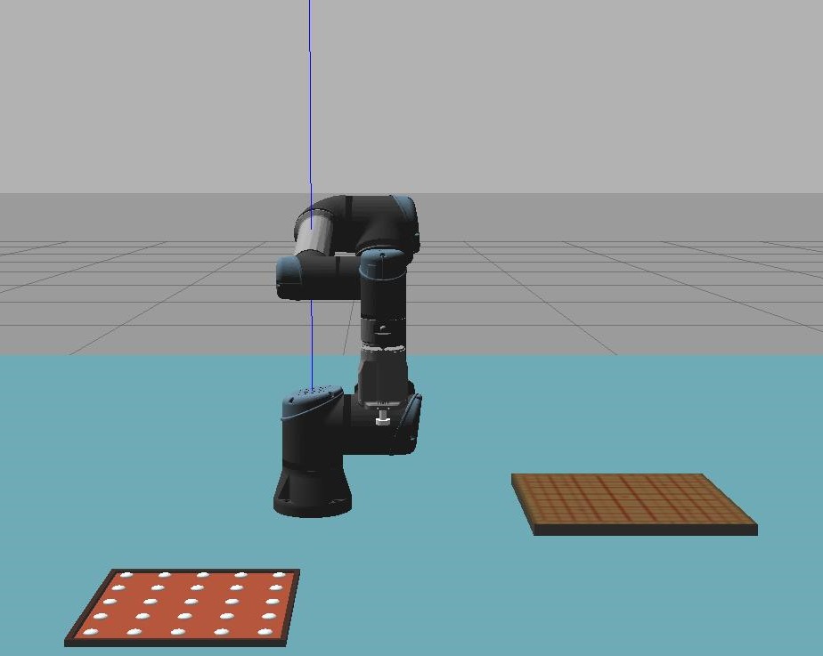
Due to the e-pick limitation(mentioned above), the game pieces on the tray had to be spaced out significantly reducing the amount that could be placed on the tray from what was planned iniitially.


- Game piece tray simplified
- Collision shape of game pieces